Basic Global Positioning System (GPS)
Introduction. The US designed NAVigation System with Timing And Ranging (NAVSTAR) global positioning system was originally designed for military use and had two modes of operation;
- a Standard Positioning Service (SPS) for civilian users and
- a more accurate Precise Positioning Service (PPS) for specially authorised users.
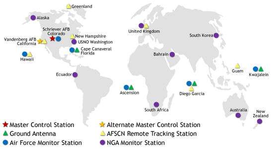
System Segments. The system is composed of three segments; the satellites in space (Space Segment), the control infrastructure on the ground (Control Segment), and the user equipment in the aircraft (User Segment). The Space Segment is a set (or constellation) of 24 orbital satellites that each transmit a signal which can be detected by receivers in the aircraft (the User Segment), and if enough satellites are in view, an aircraft position can be derived to a very high level of accuracy. The satellites are controlled by an extensive ground infrastructure located around the world (the Control Segment). These include:
- Master Control Stations
- Ground Antennas
- Monitoring Stations
As the power supplies aboard GPS satellites are limited, the signals that they transmit are not very strong. This means that the signals received by aircraft are weak and subject to interference and occasional errors; more importantly, it means that the satellites must be kept in a medium Earth orbit at an altitude of 12,550 miles – which is well below a geostationary orbit that would allow the satellites to remain stationary over a fixed point on the earth. As a result, the GPS satellites appear to rise and set twice a day, therefore only certain satellites will be visible to the aircraft at any one time.
 Principles of Operation. GPS operation is based on the concept of ranging and trilateration from a group of satellites, which act as precise reference points. Each satellite broadcasts a Navigation Message that contains the following information;
- a pseudo-random code called a Course Acquisition (CA) code, which contains orbital information about the entire satellite constellation (Almanac).
- detail of the individual satellite’s position (Ephemeris) that includes information used to correct the orbital data of satellites caused by small disturbances.
- the GPS system time, derived from an atomic clock installed on the satellite, with clock correction parameters for the correction of satellite time due to differences between UTC and GPS time (the occasional ‘leap’ second added to a year) and delays (predicted by a mathematical ionospheric model) caused by the signal travelling through the ionosphiere.
- a GPS health message that is used to exclude unhealthy satellites from the position solution.
The GPS receiver in the aircraft takes 12.5 minutes to receive all of the data frames in the navigational message. Once obtained, the receiver starts to match each satellite’s CA code with an identical copy of the code contained in the receiver’s database. By shifting its copy of the satellite’s code, in a matching process, and by comparing this shift with its internal clock, the receiver can calculate how long it took the signal to travel from the satellite to the receiver. The distance derived from this method of computing distance is called a Pseudo-range because it is not a direct measure of distance, but a measurement based on time. Pseudo-range is subject to several error sources, including atmospheric delays and multipath errors, but also due to the initial differences between the GPS receiver and satellite time references.
Using a process called trilateration, the GPS receiver then mathematically determines its position by using the calculated pseudo-ranges and the satellite position information that has been supplied by the satellites.
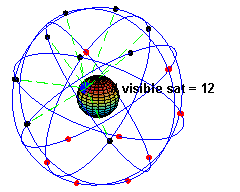
- If only one satellite is visible, position location is impossible as the receiver location can be anywhere on the surface of a sphere with the satellite at its centre.
- If two satellites are visible the receiver location can be anywhere on a circle where the surfaces of the two spheres intercept. So position location is also impossible.
- When a third satellite becomes visible, the GPS receiver can establish its position as being at one of two points on the previously derived circle where the third satellite sphere intercepts it. So, whilst position fixing is possible, it is unreliable unless it is assumed that the receiver is at sea level on the surface of the Earth, because it is almost certain that only one of the two derived points would be near the surface of the Earth. So fixing is possible, but only in two dimensions (2D fixing): in latitude and longitude.
- With at least four satellites visible, and their alignment good, the four spheres will intersect at only one point in space, so receiver position can be accurately fixed in three dimensions (3D fixing): in latitude, longitude and altitude.
- With five satellites visible, it is possible for the system to automatically detect a erroneous signal and give warnings of a loss of navigational integrity (RAIM – Fault Detection – see below).
- With six satellites visible, it is possible for the system to automatically detect a erroneous signal, identify which satellite is responsible and exclude it from consideration (RAIM – Fault Detection and Exclusion – see below).
Altitudes derived from GPS positions are known as Geodetic altitudes and were not initially used for aircraft navigation; PBN requires that they, and the navigational information presented by the system, are based on the World Geodetic System established in 1984, the WGS 84 coordinate system.
As the GPS satellites provide a very accurate time reference as well as precise 3D position fixes, they can also calculate and provide accurate speed data.
Global Navigation Satellite System (GNSS). In recent years, the NAVSTAR GPS satellites launched by the USA have been joined by the Russian GLObal NAvigation Satellite System (GLONASS) navigational satellite system. A Chinese system, BeiDou, and the European Galileo system, should become operational by 2020; other systems produced by India and Japan are also in development. Collectively, they are known as the GNSS system and modern aircraft equipment should be able to use all of them in the future.
Receiver Autonomous Integrity Monitoring (RAIM)
Given the importance placed by PBN specifications on system performance in addition to accuracy, especially during GNSS approaches, RAIM technology was developed to allow aircraft GPS receivers to assess the integrity of the GPS signals that they receive. There are now two types of RAIM technology available:
- RAIM Fault Detection (FD) This uses redundant GPS pseudo-range measurements to detect system errors. So when more than four satellites are available (the minimum needed to produce a 3D position fix), the extra pseudo-ranges should all be consistent with the computed position. A pseudo-range that differs significantly from the expected value may indicate a fault of the associated satellite, another signal integrity problem or system error. The receiver then provides an alert to the pilot that the GNSS signals are unreliable.
- RAIM Fault Detection and Exclusion (FDE) More modern GPS receivers, like the G1000, incorporate FDE technology which enables them to continue to operate in the presence of an erroneous GPS signal. Having detected a possible error, the system decides which measurement or group of measurements is more likely to be responsible for the fault and rejects the affected measurements so that they are not used in the navigation solution.
Satellites Required. As stated above, at least one extra satellite must be visible for RAIM FD to function, so at least 5 must be visible; and if the GPS receiver employs FDE, at least 6 must be visible to allow a single corrupted satellite to be excluded while still offering the needed 5 for RAIM. That said, modern systems may also employ a technique called Barometric Aiding (Baro-Aiding) whereby the altimeter feeds information to RAIM and gives it a vertical reference (an extra sphere), thereby reducing the need for one satellite signal. For more details, a useful article on RAIM (RAIM RAIM Don’t Go Away) can be found on the internet.
Accuracy. The RAIM system on the G1000 provides a RAIM protection limit of 2.0 nm for oceanic, 2.0 nm for enroute, 1.0 nm for terminal, and 0.3 nm for LNAV GNSS approaches that offer only lateral (horizontal) guidance.
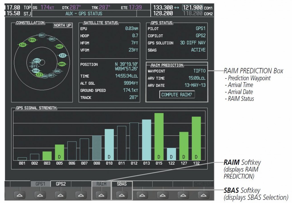
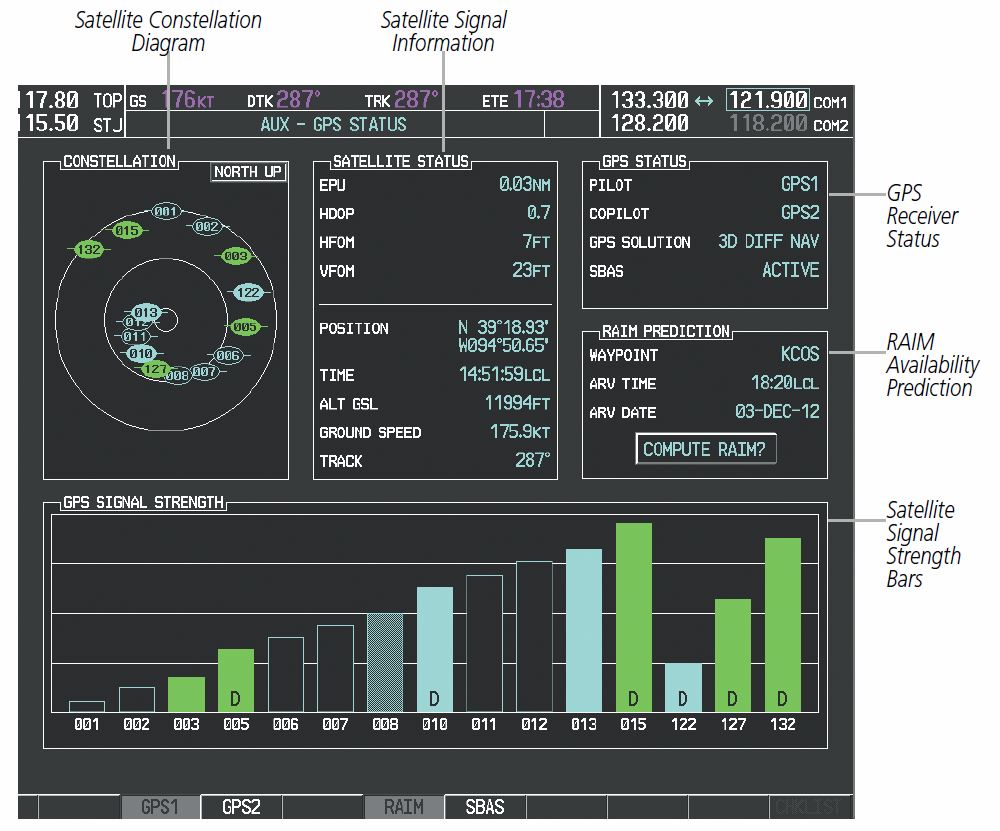
RAIM Prediction. RAIM functionality is required during an LNAV approach, so it is necessary to check if enough satellites will be visible, and in the correct orientation, to provide RAIM coverage during the period of the planned approach. This may be carried out, up to three days in advance, during the planning phase, but the G1000 also offers a RAIM availability prediction function, for use when airborne, that allows the crew to predict the availability of RAIM for the period from 15 minutes before, until 15 minutes after, the expected arrival time. It may be found on the AUX – GPS STATUS page:
However, a prediction can also be obtained from the internet before flight at the AUGUR website which includes additional warnings and information that the G1000 RAIM prediction function is not designed to provide. For this reason, it is strongly recommended that RAIM availability is checked before flight as part of the planning process; indeed, this is required by PBN if no other form of system performance monitoring is available.
Differential GPS through the use of Augmentation Systems
Whilst the basic GPS system with RAIM was accurate and reliable enough to allow area navigation and LNAV approaches, the requirement for greater accuracy and service integrity during precision instrument approaches initially prevented the use of GPS for more precise approaches to low Decision Heights.
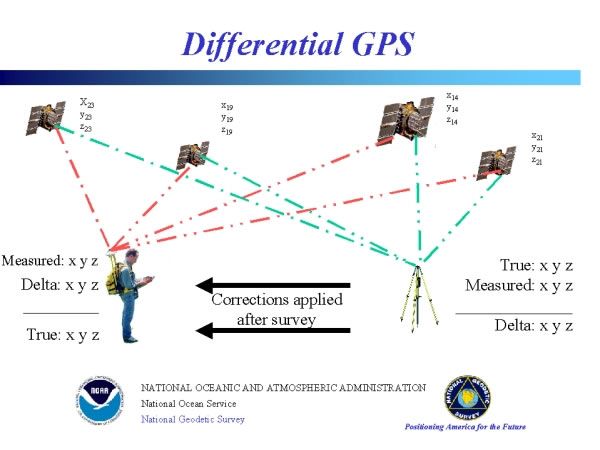
Therefore, a differential system has been introduced, through the use of augmentation systems, to improve the accuracy of GPS. These systems work on the premise that any two receivers that are relatively close together will experience similar errors. So reference GPS receiver stations were established on the ground, in precisely known locations, that could compare the GPS signals they received to their actual known location. The difference, or error, could then be fed back to specially enabled GPS receivers (Differential GPS receivers) working in that area in order to improve the accuracy of the raw GPS position. Using this system, Differential GPS (DGPS) receivers can achieve fixing accuracy in the order of 1 to 3 metres (horizontal), and 2 to 4 metres (vertical). Moreover, as the ground receiver stations also monitor the performance of GPS satellites, their service integrity is also transmitted to DGPS receivers; therefore, the resulting Augmentation signal combines differential error and system integrity messages.
Ground Based Augmentation Systems
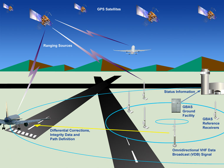
At first, DGPS receiver stations were established close to selected airfields and the augmentation signal was transmitted via VHF radio for reception by aircraft in the terminal manoeuvring area. This system is known as a Ground Based Augmentation System (GBAS).
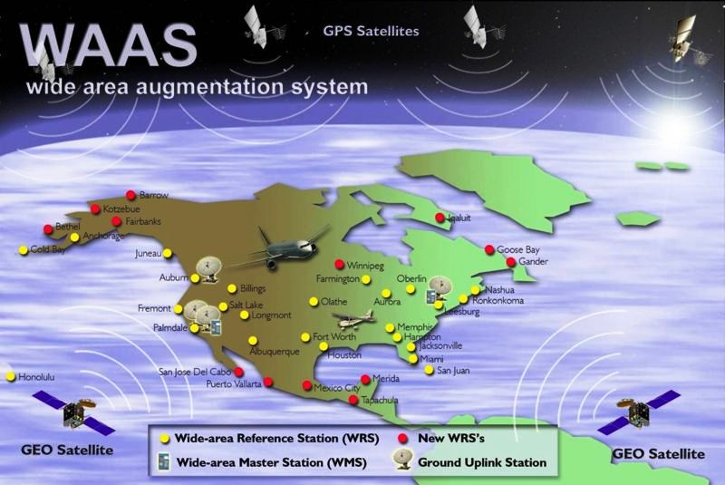
However, during 2003 the USA introduced a Wide Area Augmentation System (WAAS) that employed reference stations scattered around the USA to collect GPS performance data and transmit augmentation signals to all aircraft flying over the USA via additional satellites stationed in geostationary orbits overhead.
Known by ICAO as a Satellite Based Augmentation System (SBAS) other similar systems are being introduced around the world. In Europe, the European Geostationary Navigation Overlay Service (EGNOS), comprised of three geo-stationary satellites, was certified for use in safety of life applications during March 2011. This permits aircraft to make precision approaches using GNSS derived geodetic altitudes corrected by SBAS, for vertical guidance to airfields that have approved procedures.
SBAS Performance Monitoring
Not only does SBAS provide a DGPS system to improve accuracy, but the augmentation signal sent to the SBAS satellite for retransmission to aircraft receivers also includes additional integrity information about the whole GPS system. This is required by PBN specifications in order to permit GNSS approaches to be made using GPS derived vertical guidance as well as lateral guidance.
As SBAS provides better integrity monitoring than RAIM, once SBAS is active, RAIM predictions become unnecessary. That said, a prudent pilot would obtain a RAIM prediction during planning in case SBAS fails during flight.
Each Integrated Avionics Unit on the Seneca V is equipped with a GPS system, and each is enhanced with an SBAS receiver. On boot up, the status of each system should be viewed on the MFD by selecting the AUX – GPS STATUS page; pressing the GPS1 and GPS2 softkeys in turn will display the status in the upper right window.
 After system startup, GPS sensor annunciations sometimes occur in the CAS warning areas of the PFD when one GPS receiver has acquired satellites before the other, or one of the GPS receivers has not yet acquired an SBAS signal. Information from the GPS receiver that is producing the better solution will automatically be displayed on both PFD1 and PFD2.
In order for SBAS to function, the appropriate satellite must be selected in the SBAS Selection window (opened by pressing the SBAS softkey); for operations in Europe, EGNOS must be ticked. MSAS is the Far Eastern SBAS satellite and WAAS is the one orbiting over the USA. Only EGNOS should be ticked to prevent low strength, probably erroneous, signals being received from an incorrect satellite.
As satellites are acquired, the GPS solution improves from nothing “ACQUIRING”, through “2D NAV”, “2D DIFF NAV” and “3D NAV” to the best solution “3D DIFF NAV”. When acquisition is complete, the solution status changes to “3D DIFF NAV” and SBAS becomes “ACTIVE”.
The Satellite Status box displays the following information:
- Estimated Position Uncertainty (EPU)—A statistical error indication; the radius of a circle centred on an estimated horizontal position in which actual position has 95% probability of lying.
- Horizontal Dilution of Precision (HDOP)—Measures satellite geometry quality (i.e., number of satellites received and where they are relative to each other) on a range from 0.0 to 9.9, with lower numbers denoting better accuracy.
- Horizontal and Vertical Figures of Merit (HFOM and VFOM)—Measures of horizontal and vertical position uncertainty; the current 95% confidence horizontal and vertical accuracy values reported by the GPS receiver.
- Position – to the accuracy stated above.
- Time – from the GPS atomic clock.
- Altitude with respect to the Geodetic Sea Level.
- Groundspeed.
- Track.